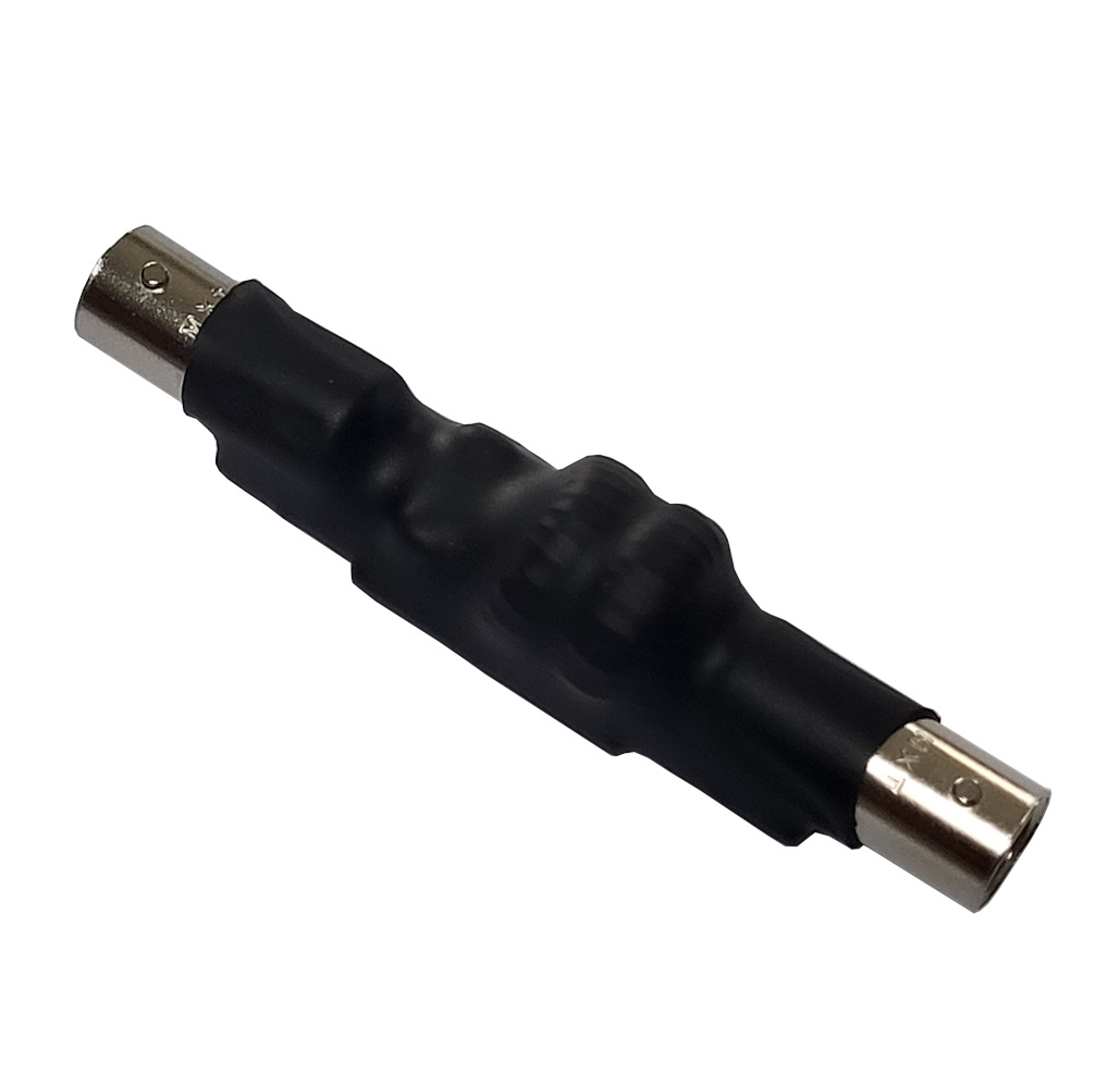
K9DP QRP BCI Filter Build Instructions
Please contact me if you have any questions.
Note: These filters have a 50 Ohm impedance and are symmetrical, so it’s not important which end is the input or output.
Caution: To ensure optimal performance and avoid damaging your filter, it’s important to use it correctly when using a tuner. The filter should be inserted inline between the transceiver and tuner, rather than between the tuner and antenna. If your radio has an internal tuner, be sure to use a resonant antenna or an antenna with a matching circuit, such as an EFHW (end fed half wave), in combination with the filter. High SWR (standing wave ratio) can potentially damage the filter.
Here’s a great build video by Temporarily Offline (Steve KM9G) YouTube channel to help walk you through the build process.
What you will need
- Soldering iron with a fine tip
- Solder (Such as Kester 63/37 with rosin core)
- Side cutter
- Knife or razor blade
- Heat gun (or an open flame for heat shrink)
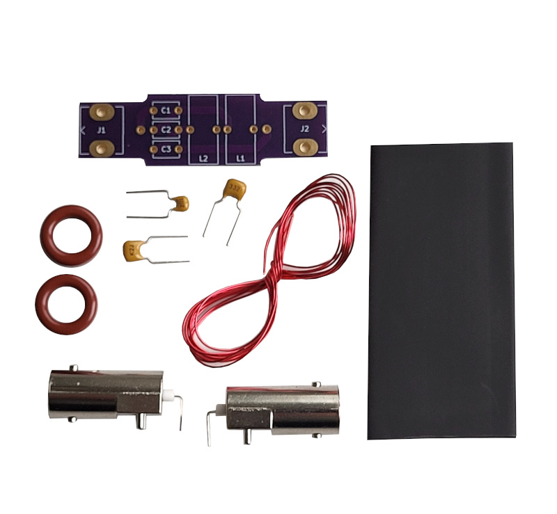
Parts List (If anything is missing contact me)
- Printed circuit board
- 2 lengths of enameled wire
- 2 BNC connectors
- 2 Toroids
- 2 3300pF capacitors (332) If you have “821” and “471″ capacitors then you have version 2 of the kit, go here for instructions.
- 1 1000pF capacitor (102)
- Heat shrink tubing
Build Instructions
1. To begin, you’ll need to attach the two BNC connectors to the circuit board. The soldering process is the same whether you have the female/female or male/female BNC versions of the kit. It is important to hold the connectors as flush with the board as possible while soldering them. To make the process easier, start by soldering the center conductor first. Once the center conductor is in place, you can then finish soldering the connector to the board.
2. You may need a magnifying glass to read the numbers printed on the capacitors. C1 and C3 on the circuit board are the capacitors labeled “332”, while C2 is the capacitor labeled “102”. If you have “821” and “471″ capacitors then you have version 2 of the kit, go here for instructions. To make it easier to solder the capacitors you can slightly bend their leads to hold them in place on the circuit board. Begin by soldering the center capacitor, C2, onto the circuit board and then trimming the leads with side cutters. Afterwards, solder the “332” capacitors onto C1 and C3 and trim their leads as well.
3. Uncoil the enameled wire and divide it into two lengths for each toroid. Start winding the first toroid, being sure to leave about 1 inch (3 cm) of extra wire at the start. Make sure to space out the wire windings evenly along the entire toroid as you wind it 24 times around. Once you reach the starting point double check you have 24 turns. Refer to pictures if you’re unsure and then cut off the excess wire, leaving about 1 inch (3 cm). Repeat this process with the second toroid, winding it the same number of times and spacing the windings evenly. Both toroids should have a total of 24 turns when you are finished.
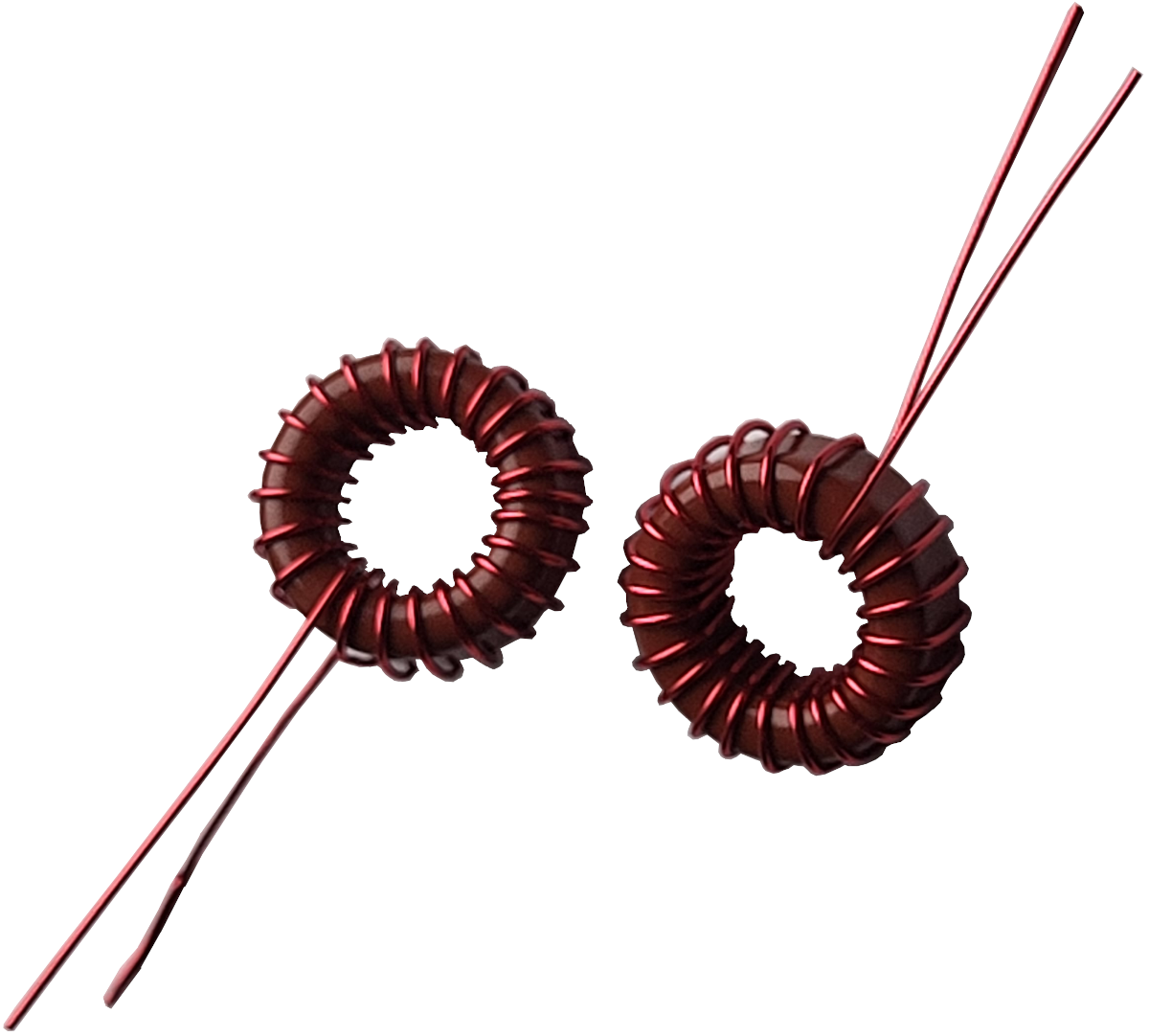
4. To ensure a solid connection with the printed circuit board, you’ll need to remove the enamel coating on the wires. Use the edge of a knife to carefully scrape off the enamel, taking care not to apply too much force and damage the wire. This process may take a bit of time, but it will be worth it to ensure a good connection.
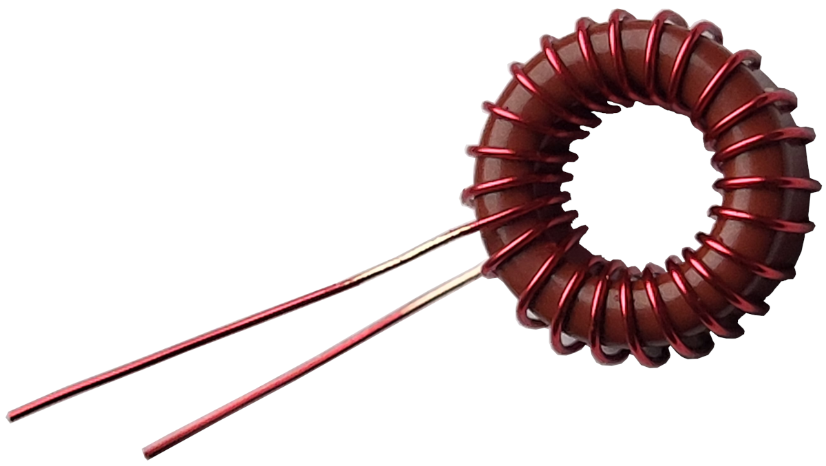
5. Feed the wires from one of the toroids into L1 on the circuit board. After passing the wires through, flip the board over and twist the wires together tightly to hold the toroid firmly in place. This will make it easier to solder. Following the same process, attach the second toroid to L2 on the circuit board.
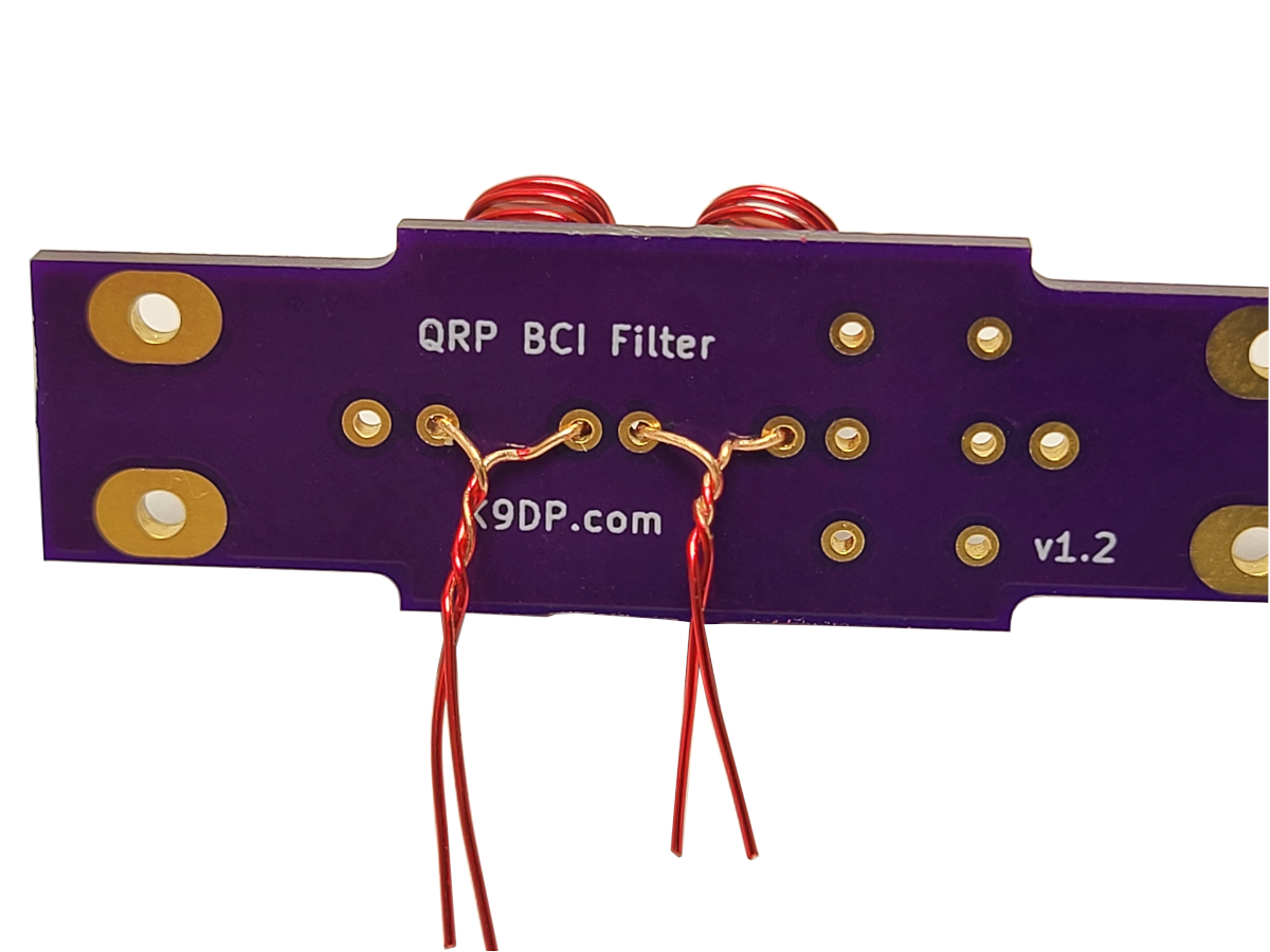
6. Once you have secured the toroids to the board, you can proceed to soldering the wires in place. After completing the soldering, use your side cutters to trim off any excess wire.
7. Before moving on to the final step, it is a good idea to check over the board and double-check your solder joints to ensure everything is in place.
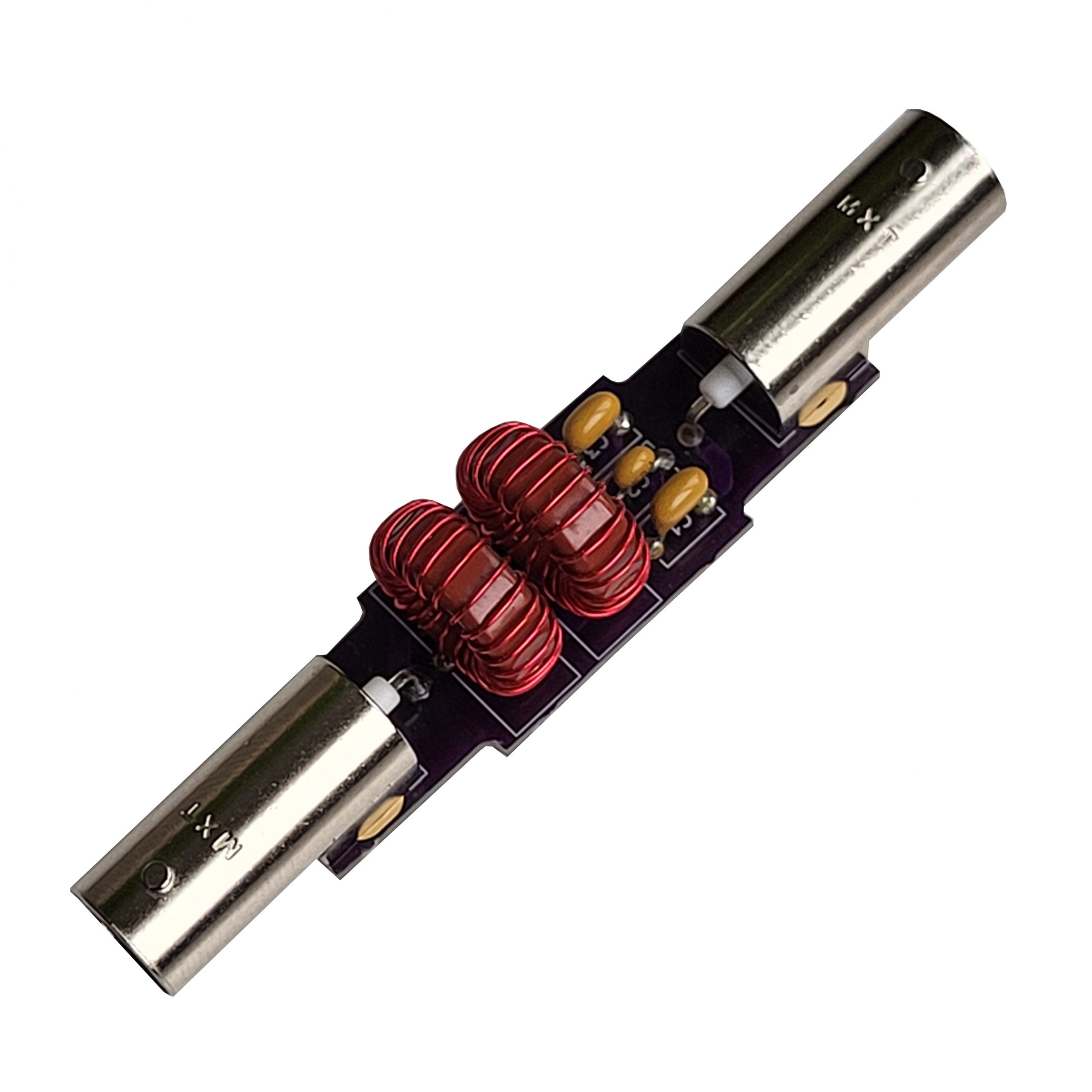
8. If everything looks good, you can test the BCI filter to make sure it is functioning properly. Once you are satisfied with its performance, you can slide the heat shrink tubing over the filter and center it as best you can. Using a heat gun, shrink the tubing in place. If you don’t have a heat gun, you can use an open flame, but be careful not to damage the tubing. Congratulations, your filter is now complete!
